How to read the Model (Computational Viewpoint)
The computational viewpoint (CV) is concerned with the modelling of computational objects and the interactions between their interfaces, according to the ODP specification [37]. The ENVRI RM uses a lightweight subset of the full ODP specification to model the abstract computational requirements of an archetypical environmental science research infrastructure.
The encapsulation of computational objects (and interfaces) occurs at a conceptual level rather than the implementation level – it is perfectly admissible for the functions of a given object to be distributed across multiple computational resources in an implemented infrastructure, should that be supported by its architecture, if that distribution does not interfere with the ability to implement all of that object's interfaces (and thus behaviours). Likewise the functionalities of multiple objects can be gathered within a single implemented service, should that be desired.
The first-class entity of the CV is the computational object:

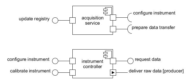
In diagrams, each a computational object is represented using a rectangle with a decoration on the upper right corner.. The text within the object indicates the name of the object. The decoration on the upper right corner is standard UML notation for component.
A computational object encapsulates a set of functions that need to be collectively implemented by a service or resource within an infrastructure. To access these functions, a computational object also provides a number of operational interfaces by which that functionality can be invoked; the object also provides a number of operational interfaces by which it can itself invoke functions on other objects. Each computational object may also have stream interfaces for ferrying large volumes of data within the infrastructure. In summary:
- Operational interfaces are used to pass messages between objects used to coordinate general infrastructure operations such as querying a data resource or configuring a service. A given operation interface must be either a server interface (providing access to functions that can be invoked by other objects) or a client interface (providing a means by which an object operations can be invoked on other objects).
- In diagrams, client and server interfaces are linked using 'ball and socket' notation: clients expose sockets (half-circles) whilst servers expose balls (complete circles).
- Stream interfaces are used to deliver datasets from one part of the infrastructure to another. A producer interface streams data to one or more bound consumer interfaces as long as there is data to transfer and all required consumers are available to receive that data (whether one, all or some of the consumers must be available depends on the circumstances of the data transfer). Data channels are typically established by operations invoked via operational interfaces (which typically negotiate the terms of the transfer), but can persist independently of them (which is useful for long-term continuous transfers such as from sensor networks to data stores).
- In diagrams, producer and consumer stream interfaces are linked using a double-arrow notation: the arrow-head points away from producers, towards consumers.
The decoration on the port boxes is not standard UML but is used to distinguish streaming interfaces.
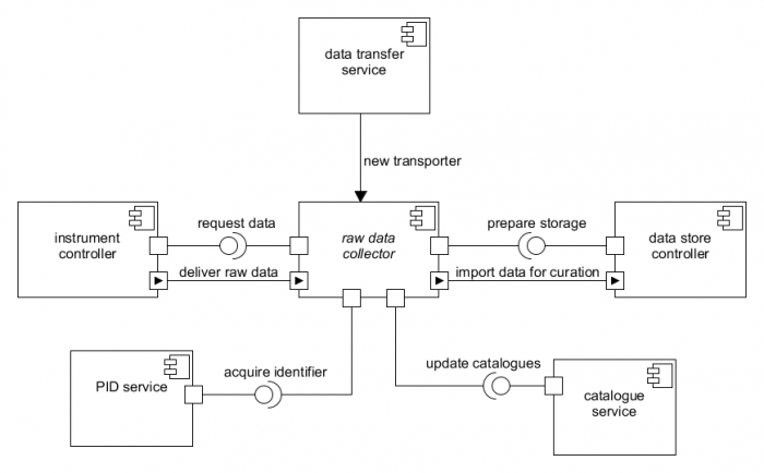
As well as having interfaces by which to interact with other objects, some computational objects possess the right to create other computational objects; this is done typically to deploy transitory services or to demonstrate how an infrastructure might extend its functionality.
Some objects extend the functionality of other objects; these objects possess all the interfaces of the parent (usually in addition to some of their own) and can be created by the same source object if the capability exists.
In diagrams, the ability to create objects is noted by a single filled arrow extending from the creating object to the object being created, with the annotation 'new <object>'. If one object extends another, then this can be illustrated using an unfilled arrow from the sub-object to the parent, with the annotation 'is a'.
Each interface on a computational object supports a certain type of interaction between objects, which determine the bindings that can be made between interfaces. A binding is simply an established connection between two or more interfaces in order to support a specific interaction between two or more computational objects. A client operational interface can be bound to any server operational interface that provides access to the functions that the client requires. Likewise a producer stream interface can be bound to any consumer stream interface that can consume the data produced by the former.
For simplicity, client and server interfaces designed to work together in the Model share the same name; thus a a client interface x can bind to any server interface x and a producer interface y can bind to any consumer interface y. When a binding is explicitly shown in a diagram, the binding itself is identified by that shared name.
Once bound via their corresponding interfaces, two objects can invoke functions on one another to achieve some task (such as configuration of an instrument or establishment of a persistent data movement channel).
Primitive bindings can be established between any client/server pair or producer/consumer pair as appropriate. Compound bindings between three or more interfaces can be realised via the creation of binding objects, a special class of transitory computational object that can be used to coordinate complex interactions by providing primitive bindings to all required interfaces.
The use of binding objects removes the imperative to decompose complex interactions into sets of pairwise bindings between objects; this suits the level of abstraction at which the Model is targeted, given that the specific distribution of control between interacting objects is often idiosyncratic to different infrastructure architectures.
The names of binding objects are typically italicised in diagrams to better distinguish them from 'basic' computational objects.
A note about implementation[edit]
In principle, all computational objects and their interfaces can be implemented as services or agents within a service-oriented architecture – this is not required however. Certain objects may be implemented by working groups or even individuals within the infrastructure organisation, bindings between their interfaces implemented by physical interactions, or otherwise human-oriented processes (such as sending data via email).
For example, in the Model, a field laboratory has the ability to calibrate instruments (represented by instrument controllers) via a binding of their common calibrate instrument interfaces. Potentially, the field laboratory could be implemented by a virtual research environment within which authorised users can interact online with instruments deployed in the field, modifying how they acquire data. In practice, the `field laboratory' may simply abstractly represent the activities of field agents (scientists and technicians) who actually travel to sites where instruments are deployed and manually make adjustments.
This possibility of this kind of 'human-driven' implementation of interactions between computational objects should be accounted for when considering the 'computational' viewpoint of a research infrastructure.


