(diff) ← Older revision | Latest revision (diff) | Newer revision → (diff)
Computational Objects[edit]
In the ENVRI RM, component diagrams are used for the representation of computational objects and interfaces.
Table 9 Notation for information object instances diagrams
| Figure
|
Description
|
|
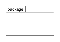
A package, in UML notation, is a grouping element. Package is used "to group elements, and to provide a namespace for the grouped elements".
A package may contain other packages, thus providing for a hierarchical organization of packages.
Classes, objects, use cases, components, nodes, node instances etc. can all be organized as packages, enabling a manageable organization of the elements of UML models.
|
|
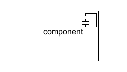
Components are used to represent computational objects. The box contains the name of the computational objet and a decoration indicating that it is a component (UML standard).
Components can also have a stereotype, and an image associated with that stereotype. In ODP the stereotype image for computational objects is the icon of a box with a class tag in front of it:
|
|
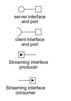
Ports and interfaces are used to represent the means of communication between objects. A small box in the border of an object is used to represent a port.
A blank circle connected by an arc to a port represents a server interface
A semicircle with an arc connected to a port represents a client interface
A port with an arc and an arrow pointing away from the object represents a producer streaming interface
A port with an arc and an arrow pointing towards the object represents a consumer streaming interface
|

|
Generalisation is used to indicate if one object extends another, this can be illustrated using an unfilled arrow from the sub-object to the parent, with the annotation 'is a'.
|

|
The ability to create objects is noted by a single filled arrow extending from the creating object to the object being created, with the annotation 'new <object>'.
|
|
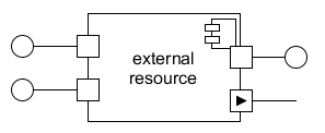
Example of a computational object with four ports and four interfaces
|
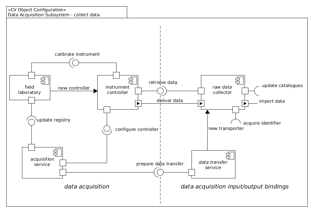
Figure 9 Example of the CV Objects for data acquisition
In the example diagram, three computational objects are presented. Balls and sockets are matched and the names of the client/server interfaces are supposed to be the same. In the example, the field laboratory client interface “calibrate instrument” is connected to the instrument controller server interface “calibrate instrument”


